eec247 Homepage

DIMMERS


Home Gallery Emergency Help Contact Us

#
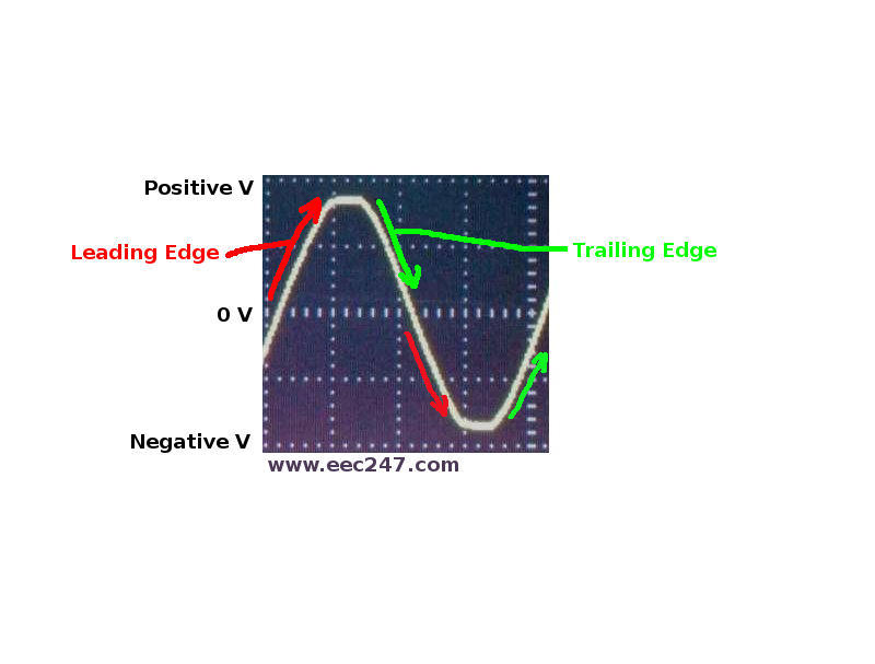
Dimmers used for domestic lighting applications come in two main types:
  • Leading Edge (the normal / standard type).
  • Trailing Edge (for dimmable LEDs and CFLs / energy saving bulbs).
Leading Edge dimmers only work with standard incandescent filament lamps (now practically obsolete) and Halogen lamps.

NOTE: Normal LED lamps and CFLs can not be used with a dimmer.
You must use dimmable LED or CFL lamps and a good quality "Trailing Edge" dimmer.


#
animation of a leading edge dimmer circuit in operation

The basic principle of a dimmer is to switch the lamp off and on very quickly.

Once the light is on, there is a separate switch to control the brightness. The on to off ratio of the "brightness" switch is set by the dimmer's brightness control and the longer the "brightness" switch is on, the brighter the light.
The action of the "brightness" switch is synchronised with the mains frequency.

LEADING EDGE V TRAILING EDGE


#
marked up photograph of an oscilloscope grab indicating leading edge and trailing edge of a mains waveform

A mains voltage changes polarity 100 times every second (50Hz or 0.020 seconds for a complete cycle).
The voltage does not flip instantaneously from one polarity to the other, but gradually changes in the form of a sine wave.
The rising slope from 0 volts, going positive is the leading edge (highlighted in red above).
The falling slope from positive, heading towards 0 volts is the trailing edge (highlighted in green above.
On the negative half cycle, heading away from 0 volts is the leading edge and towards 0 volts, the trailing edge.

The two main typed of dimmer "leading edge" and "trailing edge" refer to the edge that is used for switching for the corresponding dimmer type.

THE LEADING EDGE DIMMER AND THE WIGGLY WIRE


#
Photograph of a typical GCSE Design Technology (DT) wiggly wire in action

Anyone familiar with the GCSE Design Technology (DT) "Wiggly Wire" should recognise this photograph.

The game is to move the hoop from start to finish without touching the "wiggly wire".
If the hoop touches the wiggly wire, the buzzer sounds (even when the hoop is not touching the wire any more).
For another try, move the hoop to the start and press the reset button.

#
Circuit diagram of a thyristor based GCSE circuit - the wiggly wire

Here is the circuit diagram for the game described above.

The thyristor is the piece of electronic magic that makes it all work.
It's got three pins: The rules of the Thyristor are: This is how the "Wiggly Wire" circuit works:


#
Circuit diagram of a thyristor based simple dimmer circuit

A simplified version of the leading edge dimmer is remarkable similar to the "wiggly wire" circuit above.

It works like this:
We know from the "wiggly wire" that there must be at least 2 volts between the Gate (G) pin and the Cathode (C) pin before the thyristor will conduct.
The load in the circuit on the left is not powered up, because the Zener Diode in circuit needs 36 volts across its terminals before it conducts and we know that the thyristor needs another 2 volts on its Gate (G) pin before it operates. That's 38 volts in total and we are only supplying the drive circuit with 20 volts.

The circuit on the right has the load powered up, because we have 36 volts across the Zener Diode plus another 2 volts on the Gate (G) pin of the thyristor.
Even if the voltage on the Gate (G) pin falls to 0 Volts, the load will still powered up - once the thyristor is conducting it will continue to do so until the voltage between the Anode (A) and Cathode (C) pins falls to 0 volts.

Now that everything works with Direct Current (from a battery) it's time to see what happens with with Alternating Current (AC).
The load is not powered up until there is at least 2 volts between the Gate (G) pin and the Cathode (C) pin before the thyristor starts conducting. Then the load has power until the AC voltage reaches 0 volts.
The thyristor only conducts when the Anode (A) pin is positive relative to the Cathode pin (C), so for the negative half cycle of the AC signal, there is no power to the load.
Everything works as normal again when we are on the positive half cycle of the AC waveform.

There's a few disadvantages with this setup:

LEADING EDGE DIMMER FROM HALF WORKING TO FULLY WORKING


#
Circuit diagram of a triac based leading edge dimmer circuit

To get the half working dimmer above fully working (i.e. firing on positive and negative parts of the waveform), we make the same circuit, but with back to back parts so the switching device (triac in this case which is a pair of thyristors connected together head to tail with both gates connected together).

This is a simplified circuit, showing the basic operation of the dimmer. Real dimmers contain components to avoid causing interference to radios and TVs. In fact dimmers with faulty interference suppression components or cheap dimmers with no interference suppression can cause havoc with radios, TVs, Wi-Fi routers etc.

#
Photograph of leading edge dimmer signal with dimmer set to minimum

Voltage across lamp with dimmer (leading edge dimmer) set to minimum.

#
Photograph of leading edge dimmer signal with dimmer set to mid position

Voltage across lamp with dimmer (leading edge dimmer) set to the mid position.

#
Photograph of leading edge dimmer signal with dimmer set to the max position

Voltage across lamp with dimmer (leading edge dimmer) set to the max position.

Note also that even when the dimmer is set to maximum brightness, we never get a whole mains cycle. This is a limitation of this type of dimmer and due to the voltage drop needed by the Zener Diode (36 volts in our example) plus the voltage needed to trigger the Triac (approx. 2V). In that case we miss the first part of the AC waveform and only "see" power on the load once the mains voltage has reached at least 38 volts.

#
Trailing edge Dimmers:

Trailing Edge dimmers work with all types of dimmable lamps including incandescent filament lamps (now practically obsolete), Halogen, dimmable CFLs and dimmable LEDs.

They are more complicated in construction and operation and cost more than leading edge dimmers.


#
animation of a trailing edge dimmer circuit in operation

The trailing edge dimmer is almost identical in operation to the leading edge dimmer. The only noticeable difference is that the mains waveform is switched on the trailing edge.

To switch the waveform on the trailing edge requires more complicated electronics in the form of an integrated circuit with hundreds of components.

#
Photograph of trailing edge dimmer signal with dimmer set to min position

Voltage across lamp with dimmer (trailing edge dimmer) set to the min position.

#
Photograph of trailing edge dimmer signal with dimmer set to mid position

Voltage across lamp with dimmer (trailing edge dimmer) set to the mid position.

#
Photograph of trailing edge dimmer signal with dimmer set to max position

Voltage across lamp with dimmer (trailing edge dimmer) set to the max position.

#
Photograph of leading edge and trailing edge dimmer signals at startup

Leading edge dimmers are simple and can start running from standstill at power up as in the waveform on the left. Trailing edge dimmers (waveform on the right) need several mains cycles before they build up to full operation. The "slow start" of trailing edge dimmers is part of their normal operation, but as a side effect helps to prolong the life of incandescent filament and halogen lamps.

NOTE: All dimmers need a minimum load to operate correctly (usually 10W).
Using dimmable LEDs of less than 10W total load with a trailing edge dimmer, can give poor (i.e. unstable) results because the dimmer is running outside it's specified minimum load.

#
Dimmers and low voltage transformers:

Both Leading Edge and Trailing Edge dimmers work with conventional transformers. Most modern electronic transformers also work with dimmers but some older types do not. Electronic transformers marked "dimmable with leading & trailing edge dimmers" should work without any problem. Electronic transformers with no such labelling probably will not work.


#
Photograph of a leading edge dimmer signal through an electronic transformer with the dimmer set to min position

Voltage output from an electronic transformer with dimmer (leading edge dimmer) set to the min position.

#
Photograph of a leading edge dimmer signal through an electronic transformer with the dimmer set to mid position

Voltage output from an electronic transformer with dimmer (leading edge dimmer) set to the mid position.

#
Photograph of a leading edge dimmer signal through an electronic transformer with the dimmer set to max position

Voltage output from an electronic transformer with dimmer (leading edge dimmer) set to the max position.

#
Photograph of the test equipment used to get the waveforms for this guide

The test equipment and methods used to produce this guide are very specialised
and detailed knowledge & experience is needed to do so safely.

WARNING: Do NOT run dimmers or transformers with the internal workings exposed.
Lethal voltages are present and IT COULD KILL YOU.


eec247 Homepage