The EEC Logo

EQUIPMENT USED FOR EXPERIMENTS ON
"WHY DOES HOT WATER FREEZE FASTER THAN COLD WATER?"


#
Details of the container used in the experiments
The equipment common to all experiments is the container for the water (& ice).
They came from a Toolstation parts case ( Large Double Case ).

#
Large Double Case
The small orange containers are too small to hold anything useful, so I used the larger containers
from an old case as "donor organs" for a new case and had lots of small orange boxes free for experiments.
The dissected box above shows the construction & dimensions.

#
Containers used to freeze water for the experiments
Some boxes were used unmodified, and some modified by adding transducers or electrodes.
The 75cc container is a cut down normal container used to fill the other containers at the start of an experiment.

#
Platform used during experiments to keep container and thermocouple in identical positions between runs
This platform was used during experiments to keep container and thermocouple in identical positions
between runs and insulate the container from the metal shelf of the freezer.
The base is a an electrical surface pattress and the arm is an aluminium coat hook.
The hollow tube is of unknown origin, but could have been from a piece of self assembly furniture.
The coat hook is attached to the pattress by epoxy resin and a pair of M3 nuts and bolts.
The hollow tube at the top is a tight fit into a hole drilled into the coat hook and epoxy resined in place.

#
Test rig used for freezing experiments
The complete test rig with thermocouple and container fitted, ready for an experiment.

#
Test rig at the end of an experiment
Fluke 116 Digital multimeter with type-K thermocouple and test rig at the end of an experiment.

The "Piezo" Experiment Specific Equipment
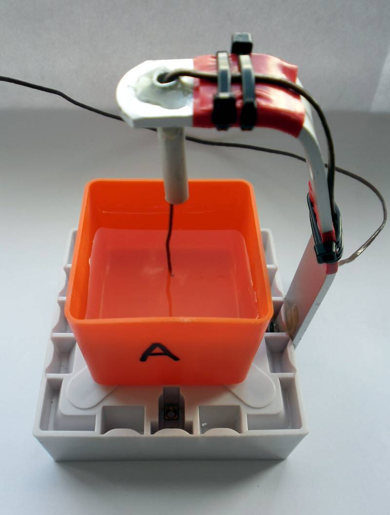
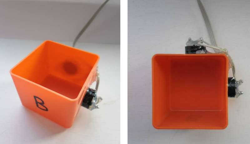
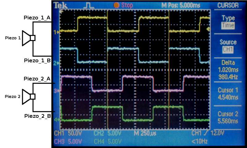
In order to determine the effect of vibration on water touching the side of the container, I attached a pair of Piezo electric transducers (similar to the type of sounder found in smoke alarms etc.) attached to some electronics to produce a sweep in frequency. The Piezo transducers were attached at 90° to each other and fed from a pair of drive voltages at 90° to each other.


#
Container "B" with piezo transducers fitted
Container "B" with piezo transducers fitted.

#
Drive waveforms for the piezo transducers
Drive waveforms for the piezo transducers.

#
sweep frequency for the piezo transducers

Sweep frequency for the piezo transducers - the frequency (pitch) of the sound from the piezo transducers
cycles through 37 spot frequencies from 100Hz to 10kHz.

#
Animation of the "Piezo" Experiment, viewed from above the container
Animation of the "Piezo" Experiment, viewed from above the container.

#
Circuit diagram of the electronics for the "Piezo" Experiment
Circuit diagram of the electronics for the "Piezo" Experiment.

#
Built and working electronics for the "Piezo" Experiment
Built and working electronics for the "Piezo" Experiment.

Click here for the Firmware used the electronics in the "Piezo" Experiment.
Due to the limited time available, this firmware was knocked together quickly from another project.
Basically, it could be tidied up a lot, but it does what I needed without too much effort.

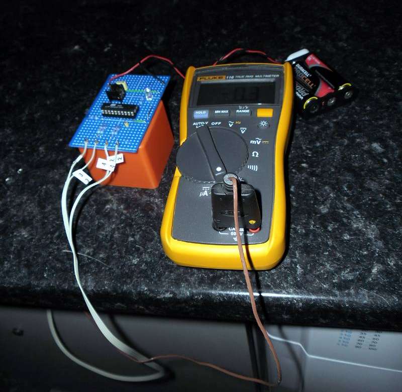
The Experiment to measure Electrical Resistance
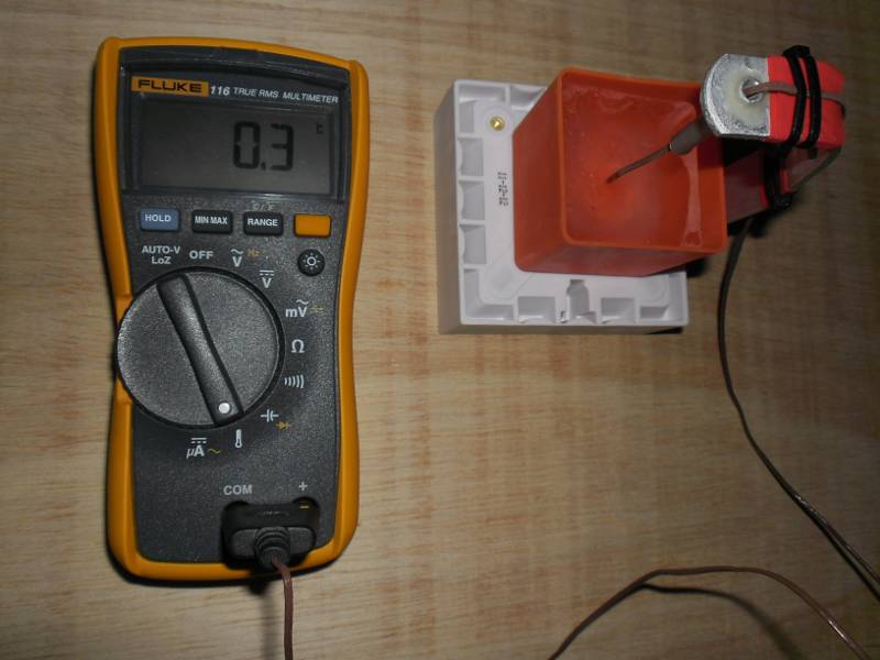
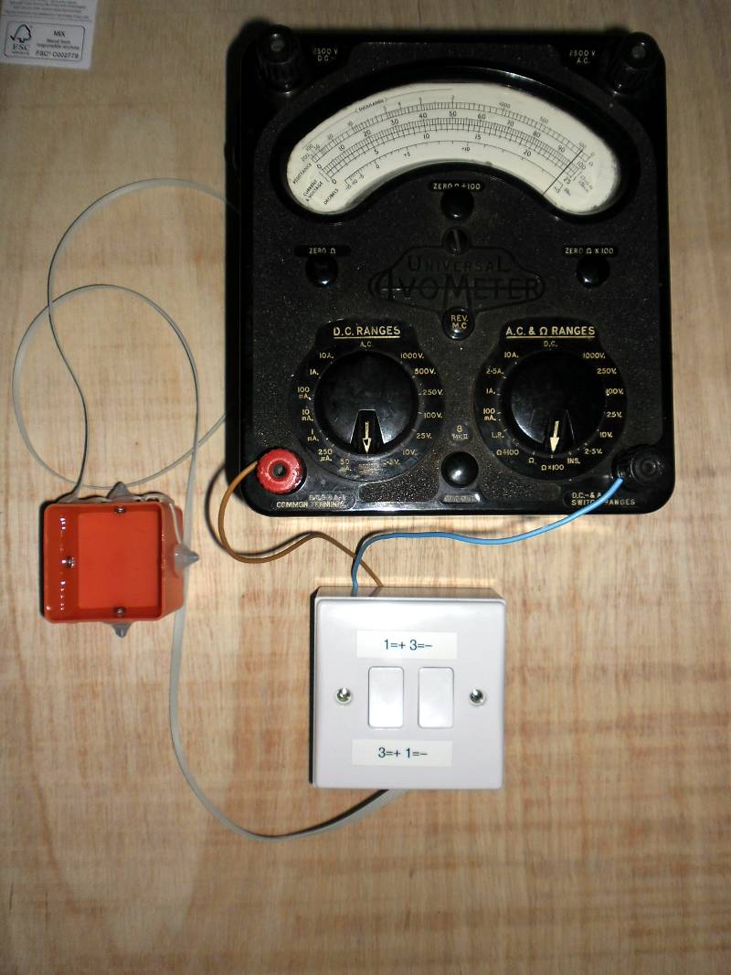
In order to determine the effect of cooling on the electrical conductivity of water
I found that the measuring the resistance with a digital multimeter was unreliable.
Even measuring resistance with an analogue meter caused unreliable results
unless the polarity was swapped between electrodes and take an average reading.


#
Container "C" with electrodes fitted
Container "C" with 4 electrodes fitted.
Only 2 electrodes (front & back in the photo above) used to measure resistance.

#
Measuring Resistance while cooling for the "Hydroxide Ion" Experiment
Circuit for measuring Resistance while cooling the samples.

#
Experiment to Measure Resistance while cooling
Physical layout of the equipment for measuring resistance.

The "Hydroxide Ion" Experiment Specific Equipment
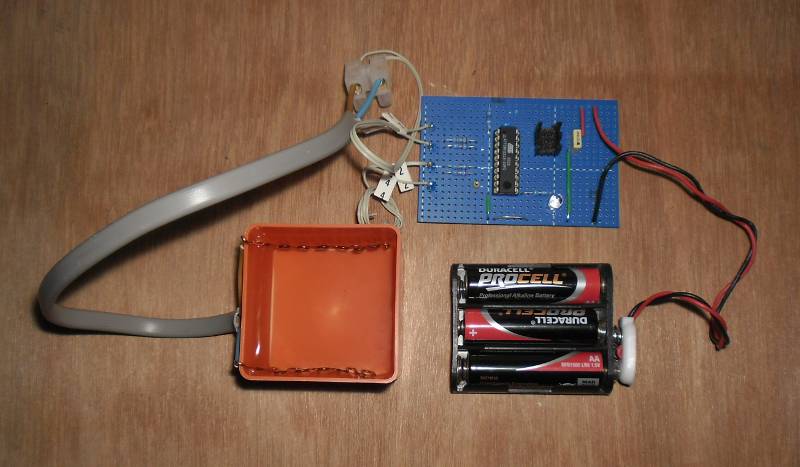
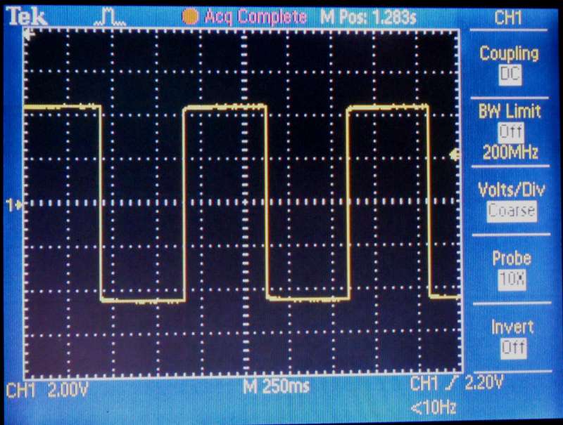
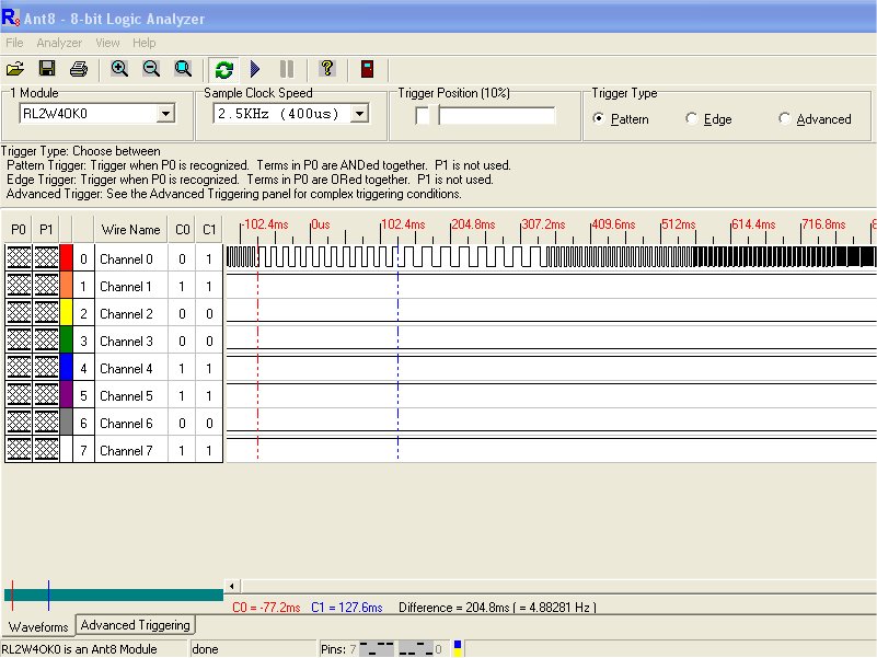
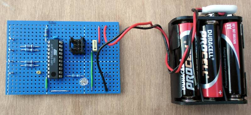
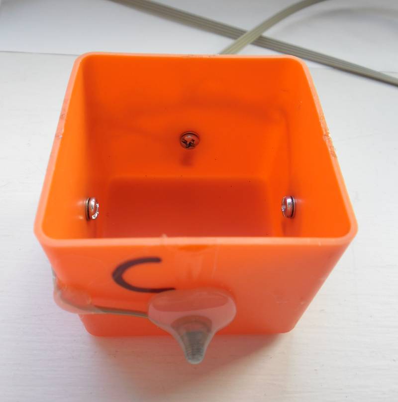
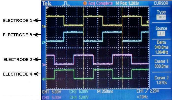
In order to determine the effect of stimulating the Hydroxide Ions of the water touching the side of the container, I attached 4 electrodes (one on each side of the container), below the water level attached to some electronics to produce a fixed 1Hz frequency fed from a pair of drive voltages at 90° to each other.


#
Circuit diagram of the electronics for the "Ion" Experiment
Circuit diagram of the electronics for the "Ion" Experiment.

Click here for the Firmware used the electronics in the "Ion" Experiment.

#
Drive waveforms for the ion electrodes
Drive waveforms for the ion electrodes.

#
Current Flow in the "Hydroxide Ion" Experiment, viewed from above the container
Current Flow in the "Hydroxide Ion" Experiment, viewed from above the container.
Basically, follow the Positive voltage on the electrodes as it rotates in a clockwise direction.

#
Animation of the "Hydroxide Ion" Experiment, viewed from above the container
Animation of the "Hydroxide Ion" Experiment, viewed from above the container.

#
The "Hydroxide Ion" Experiment in progress

The "Hydroxide Ion" Experiment in progress.

Ion Drive MK2 Specific Equipment
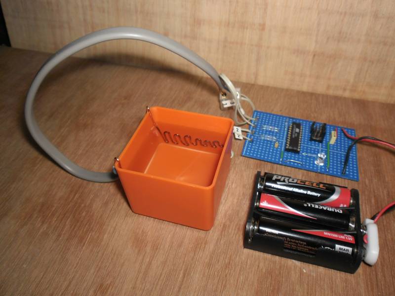
The original ion drive device gave a marginal improvement to cold samples and I learned from it's weaknesses.
Ion Drive MK2 uses exactly the same electronics & firmware as the original.
The 4 electrodes have been replaced by 2 temporary electrodes, placed in the container while the sample is being "treated".
Once the sample has been treated for a number of minutes, the electrodes are removed before the container is placed in the freezer.


#
Ion drive MK2 layout including the new electrodes
Ion drive MK2 layout including the new electrodes.

#
Ion drive MK2 showing electrode detail
Ion drive MK2 showing electrode detail.

#
Ion drive MK2 voltage waveform
Ion drive MK2 voltage waveform to electrodes.


eec247 Homepage